Power
Transformer
Technical Specification
- ✔ Copper foil winding technology is used for high current sections to achieve following advantages:
- ✔ Sustaining short circuit forces without any distortion in low voltage and high current windings
- ✔ Hot spot in LV windings regulated
- ✔ No transposition, stray losses are minimal. Thus total copper losses are also further reduced
- ✔ Total Copper losses reduced vis-a-vis standard losses. Thus heat dissipating area also reduces
Description
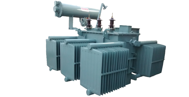
A power transformer is characterized by inner and outer low voltage winding sections and a high voltage winding section disposed there between. The low voltage windings are comprised of a plurality of pancake coils, and the high voltage winding are comprised of a plurality of conductor strands spirally wound for a plurality of coil layers. The low and high voltage winding sections are laterally spaced with the low voltage windings disposed in side-by-side positions and adjacent to the high voltage windings. The high voltage windings have a smaller turn height than the low voltage windings and have conductor strands of smaller gauge than the pancake coils of the low voltage windings.
A Power transformer is an electrical device that transfers energy between two or more circuits through electromagnetic induction.
A varying current in the transformer's primary winding creates a varying magnetic flux in the core and a varying magnetic field impinging on the secondary winding. This varying magnetic field at the secondary induces a varying electromotive force (EMF) or voltage in the secondary winding. Making use of Faraday's Law in conjunction with high magnetic permeability core properties, transformers can thus be designed to efficiently change AC voltages from one voltage level to another within power networks.
Distribution
Transformer
Technical Specification
- Range : 100 KVA to 5000 KVA
- Voltage Class : 11 KV, 22 KV, 33 KV
- Cooling : ONAN
- Taping : OFF Load Tap Changer/On load Tap changer.
Description
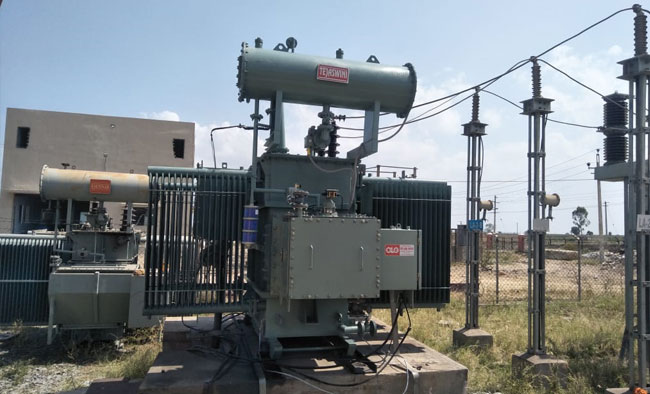
Distribution transformers for industrial application is available in 3 or 1 phase version with primary voltages of up to 33 KV and secondary voltages ranging from 433 to 11000 V. The capacity range is up to 10000 KVA. We manufacture single phase distribution transformers, three phase distribution transformers and industrial distribution transformers.
The high quality Standard setup by the company are appreciated by our customers in India and Abroad. Standards which are applied to development, manufacturing, installing and commissioning of power transformers for power stations, special purpose transformersfor industry fields,reactors and accessories.
Our manufacturing facilities are located in Hyderabad. Power transformers up to 63 MVA 132 KV Class are regularly manufactured and supplied. Tejaswini is equipped to manufacture transformers with a wide range of internationally recognized standards such as:
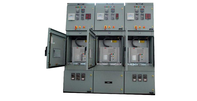
✔ Unitised substation comprises of the following main components
✔ Vacuum Circuit Breaker Panel in outdoor enclosureup to II KV.1 250 A complete with CT / PT Relay & Instrument Chamber.
✔ The outdoor circuit breaker panel is directly coupled to HT -Flange of the transformers with Copper Bus Bars.
✔ The incoming of the HT panel is provided either with plug socket or cablebox. Alternatively a Load Break Switch or Ring Main Unit (RMU)
Can also be coupled with the HT bushing of the transformer.
Outdoor transformers are manufactured up to 1600KVA, 11KV, -6.6KV-3.3 KV /415 KV DYII ONAN with off loadtap changing switch and standard fittings as per IS, incoming HT panel and LT Flange to outgoing LT Panel. The Transformers can be either oil-immersed type Or Dry type with nomex insulation. With dry type transformers the total unit can be housed in single outdoor type enclosures in place of three separate Enclosures.
Setting high Standards as a consistent guarantee of the highest quality the company have achieved ISO 9001 certification for all its transformers. Regular internal and external quality audits ensure full and continuos conformity with the international standards. The company's material and components suppliers are also required to satisfy these ISO standards
Quality control is earned out a teach stage of production on a self-assessment basic. Each employee regards the next workstation as his customer and performs a series of quality checks before passing on a product down the line. The quality development department monitors all qualitycontrol documents and carries out its own additional inspection at strategic points in the production process. This system of checks and counter checks allows immediate action to be taken and modification to be made as required. All transformer tanks are tested before being released.to the customer. Testing includes leakage test and pressure test
Winding Connections
Tapping and phase leads are run in paper-covered conductors. the phase leads being separated from the tapping leads by adequate barriers. These tubes are rigidly brazed to ensure that required clearance from coil to tank is being maintained. L.V.Leads. larger in cross section, arc generally sufficient robust. but where necessary supports are provided.
Tank Construction
All tanks are made from mild sheet of adequate thickness with pressed steel fins cooling tube for heat dissipation. All tanks are checked by magna flux ultraviolet ray die penetrating system to ensure that there is absolutely no leakage from any part of the tank.
Quality Finish Through Use Of Shot
Blasting Technology
Tanks are shot blasted/ Grit blasted to remove mill and welding scale and then a primeary coat is immediately applied to the exterior to eliminate rust formation. After priming all tanks receive a coat of high gloss paint, applied by spray. This ensures high coverage helping to combat corrosion in inacceSSible places.
Insulation And Impregnation
The principal component of insulation is insulating Pre-compressed Press Board. The Components like rings, duct , dovetailed spacers, blocks etc are put under Compression along with the coil assembly for pre-shrinking . Providing additional insultation compensates the slight recovery
This reduces Ihe probabilily of coils getting loose during operation an also minimizes the failure due to circuit forces.
In Order to prevent deformation under short-circuit forces, solid insulator end blocks and rings are used. Windings are compressed under top and bottom clamping members with the help of tie rods. The axial end thrust under fault Condition is minimized by the suitable balance to the ampere-turns over the length of windings. In case of bigger transformers, the HV taping leads are taken out from two positions to balance the short circuit forces in a much better way. At Tejaswani each and every component used in transformer undergoes a series of stringent checks and controls at each stage of manufacturing and it is ensured that strict technical & qualitative specifications are adhered to Utmost care is taken while manufacturing and assembling every component of a transformer. The main process line of a transformer is:
Core
The core is constructed from lamination of imported Cold Rolled Grain Oriented (CRGO), low loss electrical steel. The cores are assembled in jigs prior to tapping and clamping in a manner that reduces vibration and inherent varnish, which is both oil and heat resistant and complete core isconnected to the clamps to ensure that it is effectively earthen.
The Core legs are surely bound with heavy duty insulating tape and the yokes are firmly clamped between folded steel channels. Tops & bottoms clamps are secured to each other by means of tie rods which serve the dual purpose of securing the windings in the place and of transferring the load form the bottom to the top clamps when the core and windings are lifted. This prevents any tensile stress heing setup in the core legs which could adversely affect the iron losses.
Winding
Windings, or Coils are designed to meet three fundamental requirements, mechanical, Thermal & electrical. They are cylindrical in sharwand are wound concentrically. Both H.V.& L.V. windings are wounds with adequate brazing and securing tapes in order to achieve a strong and self-supporting structure. Inter layer ducts arc provided to ensure low temperature gradient between winding and oil and thus any hot spot temperature is kept to minimum. This insures that the rate of insulation deterioration is minimized and high life expectancy is achieved.
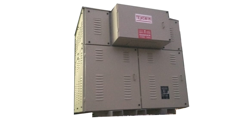
Dry Type Transformer
Description
- A Dry type transformer is a type of transformer which never uses any insulating liquid where its winding or core are immerged in liquid. Rather, the windings and core are kept within a sealed tank that is pressurized with air.
- We make VPI type (Vacuum Pressure Impregnated Transformer) This type of transformer is available up to 2.5MVA with insulation grade F(155 °) and H(180 °). It’s with Protection up to IP56.
- This type of transformer has several advantages. They are-
- High mechanical strength.
- Void free insulation
- No temperature fluctuation
- Easy maintenance
- Less prone to fire hazard
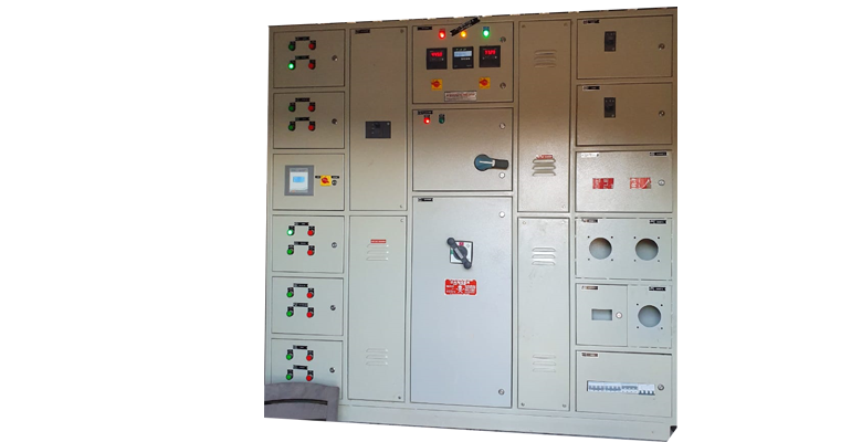
LT Panel
LT Panel
✔ All types of LT distrtibution panels
✔ Consumes less space
✔ Complete protection against bird nesting, leakage through bushing and corrosion
✔ Easy operation and maintenance
✔ Avoids direct lightning impulse
✔ Live parts are not directly accessible
✔ Loose connections are completely avoided using solid busbar system
✔ On-load protected switching system
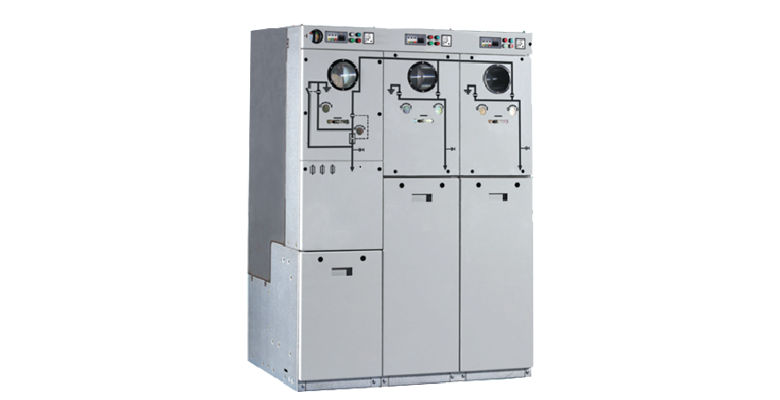
11 KV Compact Ring Main Unit
Technical Specification
- Load Break Switches or SFU
- a) 11 KV
- b) 33 KV
- Vaccum Circuit Breakers (VCB)
- a) 11 KV
- b) 33 KV
- Ring Main Unit
- a) 11 KV
- b) 33 KV
- ✔ Load Break Switch 630A, 26.3k Awith Earth Switch and Interlock, 15:9920
- ✔ Earth Fault Indicator with CBCT as per EB Standard
- ✔ VCB Type Optional
Features : (Outgoing)
- Load Break Switch 630A, 26.3 kA with fuse trip, I5:9920/ Vacuum Circuit Breaker 15:13118
- IDMT Relay Optional
- Insulation Level 12128175/ KV for LBS
- Various RMU Options (Extensible)
- RMU with 2 VCBs and LBS
- RMU with VCBs only
- RMU with LBS only
- RMU with 2 LBS and VCB
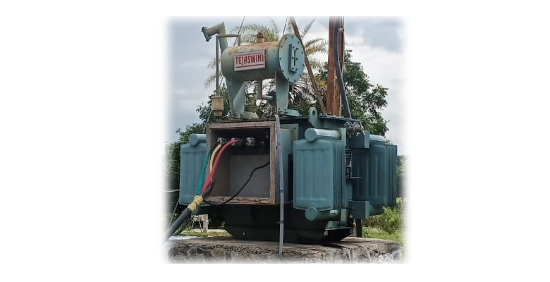
Electrical Turnkey Projects
Description
- Our vast industrial experience has made us capable us to handle Electrical Turnkey Projects. For this, we undertake all the work right from designing to commissioning of these projects.
- We possess a team of well-qualified experts who takes care all the minute details of these turnkey projects.
- Turnkey Electrical Projects means the construction of electrical project from start to end.
- It is a end to end thing in which everything will be managed by the supplier which includes the raw material required for the construction, construction process, equipments that will be used, installation and also the power supply service.
- These type of projects can be industrial, residential, commercial, etc.
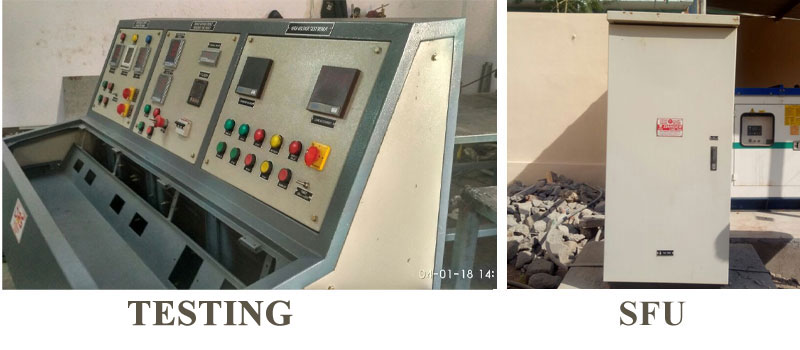
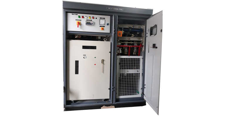
Ring Main Unit
Description
- Ring Main Unit, RMU is a compact, enclosed and sealed type of Switchgear used for medium voltage power distribution. It is a complete Switchgear in itself.
- A complete Switchgear means, assembly of required switching devices, protection device as well as metering device. RMU of different voltage (mostly 12 kV and 24 kV) and current ratings are available. Indoor as well as outdoor types of Ring Main Units are available.
- A self-powered protection device is also mounted on the Ring Main Unit, RMU. This relay is microprossor based Numerical Relay with user interface (different manufacturer have different design).
- This relay provides a limited protection such as Over Current and Earth Fault protection. Though different manufacturer offer different set of protection or manufacturer may offer protection based on the user’s specification. In distribution system, RMU is widely used as it is a complete package and only needs installation and cable connection. Everything else is within the package. This greatly reduces the commissioning time.
APFC Panel
Technical Specification
- Design Standardized Modular Sheet Steel Enclosures
- Enclosure Finish Epoxy powder coated, in grey (RAL 7305) structure finish
- Internal parts: Rust proof zinc passivated / power coated
- Rated Voltage: 415V-440V/50Hz (Design available for 380V, 480V, 690V, 750V - 50/60Hz)
- Output Rating: Other output ratings, switching combination or design voltages are available upon request
- Capacitors DUCA POWDER Super Heavy Duty Series used are rated at 525V, 690V and 880V, 50/60Hz as per network voltage
- Reactors H-Class 5.6%, 7%,14% or other Tuning/Detuning rating on request
- Incoming / Outgoing MCCB / ACB as Incomer and HRC Fuses for backup protection (other combination on request)
- Ambient Temperature 50 ° c max short time 40 ° c average in 24 hours 35 ° c annual average -10 ° c low limit
- Protection class IP 40
Description
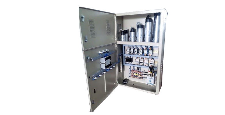
We manufacture automatic power factor correction panel that maintains the power factor of the system automatically. Fabricated using premium quality raw material with cutting edge technology, these panels are durable and dimensionally accurate. These correction controllers are installed in various places such as hotels, hospitals, commercial complexes and railways.
When the need arises to correct for poor power factor in an AC power system, you probably won't have the luxury of knowing the load's exact inductance in henrys to use for your calculations. You may be fortunate enough to have an instrument called a power factor meter to tell you what the power factor is (a number between 0 and 1), and the apparent power (which can be figured by taking a voltmeter reading in volts and multiplying by an ammeter reading in amps). In less favorable circumstances you may have to use an oscilloscope to compare voltage and current waveforms, measuring phase shift in degrees and calculating power factor by the cosine of that phase shift.
Most likely, you will have access to a wattmeter for measuring true power, whose reading you can compare against a calculation of apparent power (from multiplying total voltage and total current measurements). From the values of true and apparent power, you can determine reactive power and power factor.
Swichgears
Technical Specification
- Rated Voltage 12KV 24kV 36KV
- Rated Current 630A 630A 630A
- Rated Insulation Level 28kV /75 kV 50kV / 125kV 70 kV / 170 kV
- Rated Short time current 26.3 kA 26.3 kA 26.3 kA
- Rated Frequency 50 Hz 50 Hz 50 Hz
- Rated making current 65 kAp 65 kAp 65 kAp
- Rated off load breaking
Load Break Switch
Indoor High-voltage Air Break / Load Break Switches are based on a modular principle, which is suitable for the power system of 3.6kV to 36kV. They represent an attractive solution as a key breaking current for application in enclosed Switchgear, Ring Main Unit and Compact Substations. In combination with current limiting fuses, Switch fuse unit ensure control over the full range of over load and short circuit currents. It is used for switching the transformers, Capacitors, protecting cables and overhead lines, etc. Load Break Switch has been tested at CPRI.
Indoor High-voltage Air Break / Load Break Switches are based on a modular principle, which is suitable for the power system of 3.6kV to 36kV. They represent an attractive solution as a key breaking current for application in enclosed Switchgear, Ring Main Unit and Compact Substations. In combination with current limiting fuses, Switch fuse unit ensure control over the full range of over load and short circuit currents. It is used for switching the transformers, Capacitors, protecting cables and overhead lines, etc. Load Break Switch has been tested at CPRI.
Features:
Switch can make and break the normal rated current.
Switch can withstand short circuit making current.
Mechanism has a quick make-make and quick-break feature and the speed of make and break being entirely independent of the operator.
The handle is trip free and a trip coil can be fitted if desired.
Switch is available with Earth Switch for cable earthing with safety interlocking.
| Voltage | Type Reference | |||
| Basic Load Break Switch |
Load Break Switch + Earth Switch |
Load Break Switch + Fuse trip |
Load Break Switch + Earth Switch + Fuse trip |
|
| 3.3kV/6.6KV | G12S(N) | G12SE(N) | G12SF(N) | G12SEF(N) |
| 12kV | G12S | G12SE | G12SF | G12SEF |
| 24kV | G24S | G24SE | G24SF | G24SEF |
| 36kV | G36S | G36SE | G36SF | G36SEF |
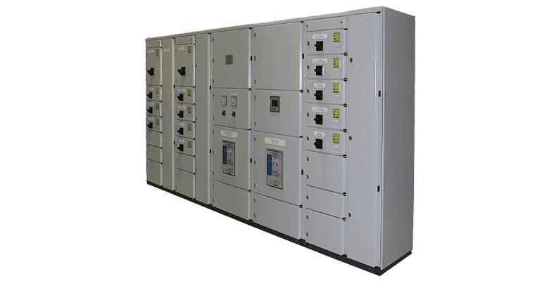
Compact modular Load Break Switch fuse Unit Panels are available suitable for Indoor / Outdoor installations. LBSFU Panels are offered with dynamic mimic and extensible on both sides. It meets the special need for Small Industries, Residential Apartments, Commercial Complexes, Hospitals, Educational Institutions, secondary substation, as well as large capacity power transformer.
LBS Panels are offered as single panel or multi line-up panels as well as Ring Main systems. The Ring Main Systems / Multi panel configuration finds application in public and industrial voltage medium voltage distribution networks.
| Rated Voltage | 12KV | 24kV | 36KV |
| Rated Current | 630A | 630A | 630A |
| Rated Insulation Level | 28kV /75 kV | 50kV / 125kV | 70 kV / 170 kV |
| Rated Short time current | 26.3 kA | 26.3 kA | 26.3 kA |
| Rated Frequency | 50 Hz | 50 Hz | 50 Hz |
| Rated making current | 65 kAp | 65 kAp | 65 kAp |
| Rated off load breaking capacity |
16A | 16A | 16A |
| Capacitor Switching Current |
25A | 25A | 25A |
| Number of Pole | Three | Three | Three |
| Number of Breaks / Pole | Single | Single | Single |
Optional Fittings:
Local / Remote Electrical Trip facility through 220V AC Shunt Trip Coil.
Auxiliary Switch contacts for local / remote ON, OFF Indications.
Note: The HT HRC fuse ratings would be in accordance with the transformer rating.
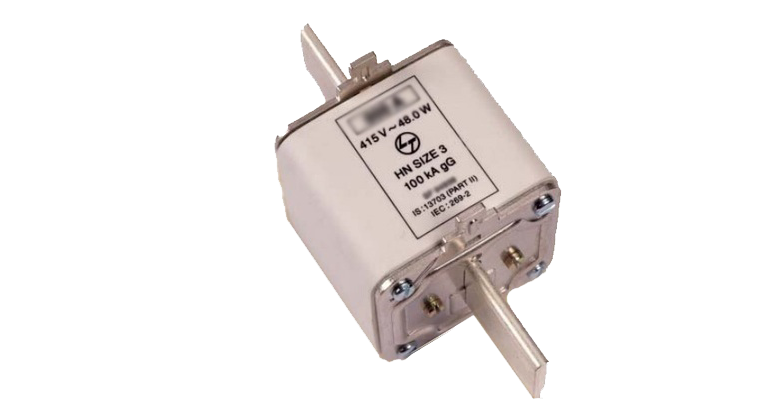
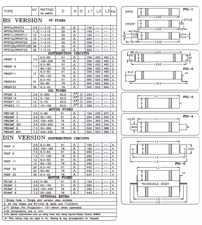
HRC Fuses
Technical Specification
- High rupturing capacity
- Short circuit current limiting
- Low rated minimum breaking current
- Dimensions according to DIN and IEC standards
- Length of the striker pin after action is 25mm to 28mm max.
Application
H.V current limiting fuse is mainly used in A.C 50.Hz rated 3.3KV to 33KV rated current from 6A to 250Aamps circuit for protecting transformers and power equipment's from Over load and short circuit. It can be used with Load break switch and Vacuum Contactor.
It conforms to IEC 60282-1 and DIN Standard
